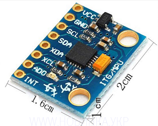
How to use MPU-6050 device with Arduino
MPU-6050 is a device which belongs to the IMU(Inertia Measurement Units) family. IMU sensors are very popular kind of sensors used in most of the embedded system projects and electronic devices. IMU sensors are used in self-balancing robots, drones, smartphones, wearable devices and more other devices to get the orientation of the device and to track movements in a 3D space.
MPU-6050 is a combination of accelerometer, gyroscope, and magnetometer. It used piezoelectric technology to sense movements. This is an accurate device and significantly cheaper than other sensors.
1. VCC – 3.3v supply
2. GND
3. SCL – A5 (arduino uno)
4. SDA – A4 (arduino uno)
5. AD0 – GND
6. INT – digital pin2 (Interrupt pin)
Figure : Interfacing MPU device with arduino
Use the given diagram to connect the device to an Arduino board. Be careful to connect 3.3v to VCC. Don't supply 5v. And also connect AD0 pin with the Arduino GND pin. You can find this device specification details going through the data sheet of the device. Click here to download the data sheet.
MPU6050 can communicate with microcontroller of arduino using I2C bus. Therefore SCL and SDA pins should connect to corresponding SCL and SDA of the micro-controller (for arduino uno SCL-analog5 & SDA-analog4). Also, this device required an interrupt pin to work. In the above circuit, it used interrupt as digital pin2 of the arduino. Because interrupt 0 (digital 2) is the pin which was defined in the example program. If you need to connect the device into another interrupt edit the below line(121) of the example code with the correct pin number.
Figure : Changing the defined interrupt pin of the example code
To work with MPU-6050 there is a library done by Jeff Rowberg. Click here to download the library files for the device. After that import the library into the library directory in Arduino. Then open your Arduino IDE and follow the below path to find the example program of the device.
File -> Examples -> MPU6050 -> MPU6050_DMP6
Before using this example code a calibration is needed to the sensor for the better use of it. Find the MPU6050 calibration code from here. Then execute the calibration code and make sure to keep the sensor horizontally until the calibration finish. After that, it will give results like below.
Then edit the example code with the offset values in the results as below.
mpu.setXGyroOffset( giroX )
mpu.setYGyroOffset( giroY )
mpu.setZGyroOffset( giroZ )
mpu.setZAccelOffset( acelZ )
Then you can use it for your project and there are several options in that example to get an output as a yaw/pitch/roll, quaternion, Euler angles and etc. Let's try work with multiple MPU 6050 in next stage.
Thank you.


Comments
Post a Comment